Tuesday, October 6, 2009

EV-DO: Evolution-Data Optimized, or Evolution-Data Only

Code Division Multiple Access 2000 (CDMA2000), consisting principally of 1xRTT and One Carrier-Evolved, Data-Optimized (1xEV-DO) versions, is the second most widely deployed cellular technology in the world with a global market share of 9.8 percent and 409 million mobile connections as of 1Q 2009. 1xRTT is the most widely deployed of the CDMA2000 family of technologies, commercial on 272 networks, and is a CDMA operator’s first step towards wireless data services. Often compared to GPRS or EDGE in the GSM family of technologies, 1xRTT has a further evolution to EV-DO.
CDMA2000 represents a family of standards and includes:
  • CDMA2000 1X
  • CDMA2000 1xEV-DO Technologies
    • CDMA2000 1xEV-DO Release 0 (Rel 0)
    • CDMA2000 1xEV-DO Revision A (Rev A)
    • CDMA2000 1xEV-DO Revision B (Rev B)
A number of operators have deployed or are deploying 1xEV-DO, where a radio carrier is dedicated to high-speed data functions. In May 2009, there were 106 EV-DO Rel 0 networks and 62 EV-DO Rev A networks deployed worldwide, according to the CDMA Development Group.
EV-DO uses many of the same techniques for optimizing spectral efficiency as HSPA, including higher order modulation, efficient scheduling, turbo-coding, adaptive modulation and coding, though the technology standards are not interoperable. For these reasons, it achieves spectral efficiency that is virtually the same as UMTS-HSPA. The 1x technologies operate in the 1.25 MHz radio channels, compared to the 5 MHz channels used by UMTS, resulting in lower theoretical peak rates, but similar average throughputs for high level of network loading. Under low- to medium-load conditions, because of the lower peak achievable data rates, EV-DO or EV-DO Rev A achieves a lower typical performance level than HSPA. CDMA operators have quoted 400 to 700 kbps typical throughput on the downlink for EV-DO Rel 0 and between 600 kbps and 1.4 Mbps for EV-DO Rev A.
Deployed network versions currently are based on either Rel 0 or Rev A radio-interface specifications. EV-DO Rev A incorporates a more efficient uplink, which has spectral efficiency similar to that of HSUPA. Operators started to make EV-DO Rev A commercially available in 2007. One challenge for EV-DO operators is that they cannot dynamically allocate their entire spectral resources between voice and high-speed data functions. The EV-DO channel is not available for circuit-switched voice, and the 1xRTT channels offer only medium-speed data. This will become an increasing problem for CDMA operators as data usage expands, and this limitation could cause suboptimal use of radio resources.
Another limitation of using a separate channel for EV-DO data services is that it currently prevents users from engaging in simultaneous voice and high-speed data services, whereas this is possible with UMTS- HSPA. Many users enjoy having a tethered data connection from their laptops – by using Bluetooth, for example – and having the ability to initiate and receive phone calls while maintaining their data sessions.
EV-DO will eventually provide service using Voice over Internet Protocols (VoIP) through EV-DO Rev A, which includes a higher speed uplink, Quality of Service (QoS) mechanisms in the network, protocol optimizations to reduce packet overhead, and will address problems such as jitter. Nonetheless, operators will face difficult choices: How many radio channels at each base station should be made available for 1xRTT to support legacy terminals versus how many radio channels should be allocated to EV-DO? In contrast, UMTS allows both circuit-switched and packet-switched traffic to occupy the same radio channel, where the amount of power each uses can be dynamically adjusted. This makes it simple for users to migrate over time from circuit-switched voice to packet-switched voice.
Beyond Rev A, Third Generation Partnership Project 2 (3GPP2) has defined EV-DO Rev B as allowing the combination of up to 15 1.25 MHz radio channels in 20 MHz – significantly boosting peak theoretical rates to 73.5 Mbps. An operator would more likely combine three radio channels in 5 MHz. Such an approach by itself does not necessarily increase overall capacity, but it does offer users higher peak data rates. As of May 2009, no operators have yet publicly committed to EV-DO Rev B.
Beyond Rev B, 3GPP2 developed Revision C standards, also known as Ultra Mobile Broadband (UMB). UMB was standardized based on an OFDMA approach like LTE and mobile WiMAX (802.16m). However, as of May 2009, no operators have committed to UMB and there are legitimate questions about the commercial viability of the technology. In fact, many mobile operators with the current EV-DO technology will likely deploy LTE because of the benefits offered by the GSM family of technologies. Leading CDMA operators worldwide including Verizon, KDDI, KTF and SKT are among those confirming that they will converge with the 3GPP world, selecting LTE over other radio access methods as they are nearing the end of their existing technology roadmap.
Though the migration from CDMA2000 to LTE is feasible, it will be more complex than migrating from UMTS-HSPA to LTE, especially in achieving interworking between LTE and legacy networks.

The CDMA2000 family of standards will continue to serve operators well into the next decade. Many CDMA2000 operators are supplementing or evolving existing networks with OFDMA technologies such as LTE to deliver advanced mobile applications that require greater network capacity and data speeds. It will be necessary to develop solutions to ensure that CDMA2000 devices, networks and roaming provide a seamless user experience across CDMA2000 to LTE wireless technology platforms.
CDMA2000 clearly is a viable and effective wireless technology and, to its credit, many of its innovations have been brought to market ahead of competing technologies. Today, however, the GSM family has in excess of 3.8 billion subscribers – more than nine times the total number of subscribers in the CDMA2000 family of technologies.

3G/UMTS

3G – History:

First generation wireless, or 1G, refers to analog networks introduced in the mid-1980s. Examples include Advanced Mobile Phone Service (AMPS) used in North America and Total Access Communications System (TACS) used in the UK. As mobile communications grew in popularity, networks often became overloaded, resulting in busy signals and dropped calls. The solution was second-generation wireless, or 2G, which emerged in the early 1990s. 2G technologies were digital and offered the much-needed capacity that 1G analog systems did not afford. Several technologies were widely used:

  • TDMA (IS-54 and IS-136)
  • GSM (a TDMA based technology)
  • CDMA IS-95 or cdmaOne (a CDMA based technology)

However, these 2G technologies are incompatible with each other. Thus, mobile service subscribers were still often limited to using their phones in a single country or region.

In an effort to standardize future digital wireless communications and make global roaming with a single handset possible, the ITU established a single standard for wireless networks in 1999. Called IMT-2000, which is commonly referred to today as 3G, the initiative set forth the requirements (mentioned above) for the third generation of wireless networks.

evo-3g.jpg

3G – The Standard:

3G stands for third-generation wireless technology and networks. The concept of a single standard evolved into a family of five 3G wireless standards. Of those five, the most widely accepted are CDMA2000, WCDMA (UMTS) and TD-SCDMA. According to the ITU and IMT-2000, a wireless standard must meet minimum bit-rate requirements to be considered 3G:

  • 2 Mbps in fixed or in-building environments
  • 384 Kbps in pedestrian or urban environments
  • 144 Kbps in wide area mobile environments
  • Variable data rates in large geographic area systems (satellite)

In addition to providing faster bit rates and greater capacity over previous-generation technologies, 3G standards excel by effectively:

  • Delivering mobile data
  • Offering greater network capacity
  • Operating with existing second-generation technologies
  • Enabling rich data applications such as VoIP, video telephony, mobile multimedia, interactive gaming and more

3G Today:
Today, WCDMA (Wideband CDMA) and CDMA2000 are by far the dominant standards in terms of current commercial services, operator deployment plans and vendor support. Launched commercially by wireless operators in 2000, CDMA2000 1X was the world’s first operational 3G technology, capable of transmitting data faster than most dial-up services. Today, more than 190 million people enjoy the benefits of CDMA2000 1X, which provides enhanced data capacity compared to all 2G technologies.

Also known as UMTS (Universal Mobile Telecommunications System), WCDMA (Wideband CDMA) is the 3G standard chosen by most GSM/GPRS wireless network operators wanting to evolve their systems to 3G network technology. WCDMA offers enhanced voice and data capacity and peak data rates faster than most dial-up services and average rates consistently greater than GSM/GPRS (Global System for Mobile communications/General Packet Radio Service) and EDGE (Enhanced Data for GSM Evolution). As of February 2006, more than 51 million subscribers were using WCDMA for their mobile voice and data needs.

Architecture:

UMTS_architecture

Sunday, October 4, 2009

EDGE / GPRS / EVDO

In Bangladesh, the mobile phone companies emphasized mainly on voice service upto the end of 2005. Since then, the operators are introducing newer and modern technology to meet the data communication requirement of the clients. Other countries adopted those features long ago, specially the GPRS. GrameenPhone is the pioneer in introducing this type of data service to the people of Bangladesh. When GrameenPhone offered the service as a trial basis, Aktel announced the same sort of service… However, GP started staying a step ahead by offering EDGE where as Aktel started with GPRS. More over, after the trial period (to some selected users) GP’s service was available to both prepaid and postpaid customers. Aktel offered the service to both type of users recently prior to what the service was only available to the post paid users. Banglalink on the other hand offered GPRS to its postpaid Enterprise users from the beginning of 2007, depriving the prepaid and normal postpaid users. TeleTalk has offered reasonable packages for both prepaid and postpaid users. Infact teletalk is the only operator to offer unlimited usage package to the prepaid users also. Warid started its operation with the GPRS facilty, but yet to offer any unlimited usage package. Citycell, country’s only CDMA operator, has however started its data service after adopting CDMA 2000 1xRTT technology country wide. The data service technology by Citycell is known as EVDO (Evolution-Data Optimized). The service name is “My Citycell Zoom” and is only availble for the post paid users again depriving the prepaid users. Moreover, the package has flavor of both the time validation and data limit. This is not as cheap as the unlimited offers by the other operators nor as expensive as the Taka/MB offers.

Tariff plan for EDGE/GPRS/EVDO service:

General Packet Radio Services (GPRS) simply is an extension of the GSM standard to provide packet data services. It was introduced in late 2000. It can provide data rates from 56 to 114 Kbps and continuous connection to the Internet for mobile phone and computer users.

Enhanced Data rates for Global Evolution (EDGE) is a radio based high-speed mobile data standard. It allows data transmission speeds upto 384 kbps to be achieved when all eight timeslots are used. In fact, EDGE was formerly called GSM384. This means a maximum bit rate of 48 kbps per timeslot. Even higher speeds may be available in good radio conditions.

EVDO or Evolution Data Only/Evolution Data Optimized (often abbreviated as EVDO, EV-DO, EvDO, 1xEV-DO or 1xEvDO) provides fast wireless broadband (3G) internet service. EVDO is based on the 1xRTT standard, which is available in almost all cell phone coverage areas and provides Internet speeds of about 2-3 times that of dial-up (about 60K-100K).

A comparison between different Data Standards:

UMTS Network Architecture

1. Introduction

Universal Mobile Telecommunication System (UMTS) currently viewed as a dream system that replaces the Global System for Mobile Communication (GSM). UMTS is an evolution satau third generation (3G) mobile networks. UMTS also shows the growing demand of mobile applications and Internet applications for new capacity so that the world increasingly crowded mobile communications. Increase network transmission speeds up to 2 Mbps per mobile user and set a standard of global exploration.

UMTS, also called Wideband - Code Division Multiple Access (W-CDMA). This system allows many different applications to be introduced into the corners of the world to mobile users and provides an important link between the present GSM system, and the last of the worldwide standard for the entire single mobile telecommunications, International Mobile Telecommunications-2000 (IMT-2000 ).

2. IMT-2000

The main characteristics of 3G systems that we know as the IMT-2000, is one family that have standards and have campatible following characteristics:

* Used throughout the world
* Used for all mobile applications
* Support for data transmission from the packed-switched and circuit switched
* Offers a high data rate up to 2 Mbps
* Offer high spectrum efesiansi

IMT-2000 is a set of requirements issued by the International Telecommunications Union (ITU). BMI represents the International Mobile Telecommunications, and describes the year 2000 which is scheduled for the beginning of the experiment system and the frequency range of 2000 MHZ (WARC'92; 1885-2025 MHz and 2110-2200 MHz). All 3G standards have been developed by regional standards developing organizations (SDOs). On the whole proposal was submitted by regional SDOs in the ITU in 1998 as many as 17 different proposals for IMT-2000 standard, 11 proposals for terrestrial systems and 6 proposals for mobile satellite systems (MSSs). At the end of 1998 it had evaluated the proposal in full, and in mid-1999 has been negotiated at a different consensus view that 17 proposals have been approved as an IMT-2000 standard by the ITU.

Most of the IMT-2000 proposals are UMTS (W-CDMA) as the successor of GSM, CDMA2000 as a temporary replacement for the standard '95 (IS 95), and time division - synchronous CDMA (TD-SCDMA) (universal wireless communications-136 [ UMC-136] / EDGE) as the basis for improving TDMA D-AMPS/GSM.

Most of the IMT-2000 proposals are UMTS (W-CDMA) as the successor of GSM, CDMA2000 as a temporary replacement for the standard '95 (IS 95), and time division - synchronous CDMA (TD-SCDMA) (universal wireless communications-136 [ UMC-136] / EDGE) as the basis for improving TDMA D-AMPS/GSM.

UMTS allows many applications to be introduced to users across the world and provides a variety of the most important link of the system in the present GSM and IMT-2000. The new network should also show growth in demand from mobile and Internet applications for new capacity in the world of mobile communications that have been solid. Increased transmission speed UMTS up to 2 Mbps per mobile user and set a standard of global exploration.

UMTS is developed by Third-Generation Partnership Project (3GPP), a joint venture of several SDOs - ETSI (Europe), Association of Radio Industries and Business / Telecommunication Technology Committee (ARIB / TTC) (Japan), American National Standards Institute (ANSTI) T-1 (USA), Telecommunication Technology Association (TTA) (South Korea), and Chinese Wireless Telecommunication Standard (CWTS) (China). To reach global acceptance, 3GPP is introducing UMTS in phases and annual releases. The first release (UMTS Rel. '99), Introduced in December 1999, this shows an improvement and replacement for the existing GSM networks. For the second release (UMTS Rel. '00), The same change is proposed as improvements to the IS-95 (with CDMA2000) and TDMA (with TD-CDMA and EDGE).

The most important changes in Rel. '99 Is a UMTS Terrestrial Radio Access (UTRA), a radio interface for W-CDMA land-based communications. UTRA supports Time Division Duplex (TDD) and Frequency Division Duplex (FDD). TDD model optimized for public micro and pico cells and cordless applications without a license. FDD model is optimized for a wide range of areas, namely; public macro and micro cells. Both models offer tersubut data rate dynamic and flexible up to 2 Mbps. The model described UTRA others, multicarrier (MC), is expected to be compatible between UMTS and CDMA2000.

edge1.jpg

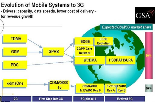
Figure Scheme UMTS Evolution

3. The UMTS network Arsistektur

UMTS (Rel. '99) unites the increase of the GSM phase 2 + Core Network with GPRS and CAMEL. Enables network operators to enjoy increased efficiency because the cost of UMTS 2G can protect investments and reduce the risk of these implementations.

In UMTS release 1 (Rel. '99), has introduced a new radio network kases UMTS Terrestrial Radio Access Network (UTRAN). UTRAN, UMTS Radio Access Network (RAN), can be connected to the GSM phase 2 + Core Network (CN) via Iu. A UTRAN Iu interface between the Radio Network Controller (RNC) and CN; UTRAN interface between RNC and packet-switched domain of CN (Iu-PS) is used for PS data and the UTRAN interface between RNC and the circuit-switched domain of CN (Iu - CS) was used for the CS data.

Mobile Stations (MSS) "GSM-only" will be connected to the network via the GSM air (radio) interface (Um). UMTS / GSM dual-mode user equipment (UE) will be connected to a UMTS network over the air (radio) interface (Uu) on the data rate is very high (close to 2 Mbps). Outside the service area of the UMTS, UMTS / GSM UE will be connected to the network by reducing the data rate through Um.

Maximum data rate is 115 kbps for CS data by HSCSD, 171 kbps for PS data by GPRS, and EDGE 553 kbps by. Support handover between UMTS and GSM, and handover between UMTS and other 3G systems (eg, multicarrier CDMA [MC-CDMA]) will be able to support all around the world access to the right.

Public Land Mobile Network (PLMN) described in UMTS Rel. '99 Unites major kategari of 3 network elements:

Phase ½ * GSM core network elements; mobile service switching center (MSC), visitor location register (VLR), home location register (HLR), authentication center (AC), and equipment identity register (EIR).
* GSM Phase 2 + enhancements; GPRS (serving GPRS support node [SGSN] and the gateway GPRS support node [GGSN]) and CAMEL (CAMEL service environment [CSE])
* Improvement and UMTS specific modifications, especially the UTRAN.

3.1. Network elements of GSM Phase ½

½ PLMN GSM phase contains from 3 subsystem; base station subsystem (BSS), network and switching subsystem (NSS), and operations support system (OSS). BSS contains a few functional units; base station controller (BSC), transcievier base station (BTS) and transcoder and rate adapter unit (Trau). NSS contains several functional units; MSC, VLR, HLR, EIR, and AC. Seoerti MSC provides switching functions, signaling, paging, and inter-MSC handover. OSS includes operation and maintenance centers (OMSs), which is used for remote operation and Centralized task, administration, and maintenance (OAM).

umts3.jpg

Phase UMTS network Figure 1

3.2. Network elements of GSM Phase 2 +

3.2.1. GPRS

Most important from the evolutionary GSM to UMTS is GPRS. PS introducing GPRS into GSM CN and allow direct access to packet data networks (PDNs). PS This transmission allows for high data rates well beyond the 64 kbps limit of ISDN through the GSM CN, the data transmission rate for UMTS is required up to 2 Mbps. GPRS will prepare and CN menoptimalisasi for high data rate PS transmission, as well as UMTS with UTRAN the RAN. As such, GPRS is a prerequisite for the introduction of UMTS.

Two of these functional units extends from the architecture to the GSM NSS PS GPRS services; GGSN and SGSN, GGSN has the function of comparing the gateway MSC (GMSC). SGSN is at the same hierarchical level as the visited MSC (VMSC) / VLR and carry out comparable functions like routing and mobility management.

3.2.2. CAMEL

CAMEL enables worldwide access to the operators who use IN applications such as prepaid, call screening, and supervision. CAMEL is a major increase in GSM phase 2 + to the introduction of the concept of UMTS virtual home environment (VHE). VHE is a platform of flexible service definition (collection from service creation tool) that allows operators to modify or penigkatan existing services or create new services. Moreover, VHE enables worldwide access to operator-specific services in every GSM and UMTS PLMN and introduces location-based services (by interaction with the GSM / UMTS mobility management). A CSE and a new protocol of the common control signaling system 7 (SS7) (CCS7), CAMEL application part (CAP), used in the CN to introduce the CAMEL.

3.3. UMTS network elements of Phase 1

Has been mentioned above, that different UMTS with GSM phase 2 + most of the new principles for air interface transmission (W-CDMA instead of TDMA / FDMA). Therefore, a new RAN is called UTRAN must be introduced with UMTS. Only projection modifications, such as the allocation of trnascoder (TC) function for voice emphasis on the CN, the CN is required to accommodate the change. The function TC is used in conjunction with the interworking function (IWF) for protocol conversion between the interfaces A and Iu-CS.

3.3.1. UTRAN

UMTS standard can be seen debagai an extension of the existing network. Two new network element has been introduced in the UTRAN, RNC, and Node B. Divided again in the UTRAN radio network system (RNSs) the individual, where each RNS is controlled by the RNC adalan. RNC is connected to a set of Node B elements, which each Node B can serve one or several cells.

umts4.jpg

Figure UMTS phase 1: UTRAN

Existing network elements, such as MSC, SGSN, and HLR, front extended to adopt the UMTS requirements, but the RNC, Node B, and the new handsets to be designed all. RNC will be a replacement for BSC, and Node B will function almost the same as the BTS. GSM and GPRS networks will be developed, and new services will be integrated into the overall network that contains both the existing interfaces such as A, Gb, and Abis, and including the Iu which is a new interface, UTRAN interface between Node B and RNC (Iub), and the UTRAN interface between two RNCs (Iur). new open interface in UMTS:

* Uu: UE interface to Node B (UTRA, the UMTS W-CDMA air interface)
* Iu: RNC interface to GSM phase 2 + CN (MSC / VLR or SGSN), which consists of the Iu-CS is used for data communications circuit-switched and Iu-PS is used to communicate packet-switched data.
* Iub: RNC to the Node interface B
* Iur: RNC to RNC interface, not comparison to other interfaces in GSM

RNC allows autonomy from the radio resource management (RRM) by the UTRAN. RRM perform the same functions as the GSM BSC, providing central control Untk RNS elements (RNC and a Node B). RNC handles protocol exchanges between the interfaces Iu, Iur, and Iub and is responsible for Centralized operation and maintenance (O & M) of the entire RNS with access to the OSS. Because the ATM-based interface, RNS ATM cell transfer between the interfaces Iu, Iur, and Iub. The user data in circuit-switched and packet-switched interface besaral of Iu-CS and Iu-PS is multiplexed together for multimedia transmission via Iur interfaces, Iub, and Uu to and from the EU.

RNC using the Iur interface, which is not the same as in GSM BSS, the autonomy to handle 100 percent of the RRM, removing the burden from the CN. Serve functions such as admission control, connection to the EU PRC, or macro diversity handover and congestion fully regulated by the serving RNC (SRNC) single. If another RNC is involved in the active connections through a soft inter-RNC handover, declared as a drift RNC (DRNC). DRNC only responsible for the allocation of the source code. A possible to re-allocate from SRNC to DRNC functions of the previous (re-allocation of serving radio network subsystem [SRNS]). Part of the controlling RNC (CRNC) is used to describe the RNC that control the logic resources of UTRAN access points.

3.3.2. Node B

Node B is a physical unit of the transmission / reception radio using the cell. Depending on sektorisasinya (omni / sector cells), one or more cells can be served by node B. A single Node B can support both models of the FDD and TDD, and the model may be co-located with GSM base stations to reduce the cost of implementation. Node B is connected with the EU through the radio interface Uu W-CDMA and connected to RNC via the Iub interface-based ATM. Node B is the point of the ATM terminal. The main task of Node B is to convert data from and to the radio interface Uu, including forward error correction (FEC), adaptation values, spreading / despreading W-CDMA, and modulation Quadrature phase shift keying (QPSK) at the air interface. Node B measures the strength and quality of connections and determine the frame error rate (FER), data transmission is addressed to the RNC as a measurement of the handover report, and a combination of macro diversity. Node B is also responsible for the FDD softer handover. The combination of micro diversity is free, remove the need for additional transmission capacity in the Iub.

Node B also beparsitipasi in power control, as something that allows for adjustment of the downlink using the command (DL) transmission power control (TCP) through the inner-loop power control information based on the uplink (UL) TCP. Values that are known from the inner-loop power control comes from the RNC via outer-loop power control.

umts6.jpg

Figure Overview Node B

4. Reference

* Http://www.iec.com [the international engineering consortium]
* Http://www.umtsworld.com [news and information about 3G mobile networks]

EDGE (Enhanced Data rates for GSM Evolution)

1. Development of Mobile Communications Technology

The development of mobile communication technology to walk very fast. In a relatively short time, since diperkenlakannya using AMPS as mobile communication technology in the first generation tahung 1978, up to now (in 2006), its development of technology has reached the 4th generation, although still under research and testing. GSM itself as one of the technology a second-generation mobile communications, is a technology that is currently the most widely used in various countries. In the process, GSM is able to deliver voice communications and low speed data (9.6 - 14.4 kbps), then developed into a capable GPRS voice and also distribute the data with better speed, 115 kbps. In the next phase, the need for a mobile communication system capable of distributing data with higher speeds, and to respond to this need and introduced EDGE (Enhanced Data rates for GSM Evolution) is able to deliver data at speeds up to 3 times the speed of GPRS, which is 384 kbps.

In further development, third-generation technology was introduced, one of which UMTS (Universal Mobile Telecommunication Service), which can deliver data at speeds up to 2 Mbps. With speeds up to 2 Mbps, UMTS networks can serve multimedia applications (video streaming, Internet access or video conferencing) via mobile devices quite well. Perkembangandi world of mobile telecommunications is believed will continue to grow, until eventually introduced new technologies better than the current yangada. Lately, scientists trying to develop a mobile telecommunication technology with a very wide bandwidth, high mobility rates, integrated services, and berbasikan IP (Mobile IP). This technology was introduced with the name "Beyond 3G" or 4G.

edge1.jpg

2. EDGE implementation

As the name suggests, EDGE (Enhanced Data rates for GSM Evolution), is a technology developed with the basic GSM and GPRS technologies. The EDGE system is developed by using equipment that remain are on the GSM / GPRS network. So can not EDGE alone. A GPRS system consists of the SGSN (Serving GPRS Support Node) and GGSN (Gateway GPRS Support Node), which is corenya network, which added to a previous GSM network. While on the radio, GPRS network requires the addition of PCU in GSM network radio devices before. The figure below shows the GPRS network diagrams in general.

gprs.jpg

Implementation of existing EDGE GPRS network requires only the addition of the radio access side only. While on the side of its core network, EDGE uses the device and protocol similar to that used in previous GPRS network. Differences GPRS and EDGE networks only in akssnya radio side only, while on the corenya networks, EDGE and GPRS equipment and using the same protocol. A GPRS network can be upgraded into a network with EDGE system by simply adding a Transceivier EDGE Unit (TRU) on the side of the radio access. The figure below shows the block diagram of a GPRS network is upgraded to EDGE in general.

edge4.jpg

3. How EDGE Speed That Can Achieve?

EDGE is a way to increase data speeds on GSM radio link. Using modulation techniques and coding schemes are different from the previous GPRS system, and by setting the protocol radio link, EDGE offers a thoughput capacity and significantly greater than that owned by the GPRS system. So in general there are three aspects of new techniques to EDGE if we compare with the GPRS, namely:

* Modulation Technique
* Coding Techniques
* Radio Access Network (RAN)

3.1. EDGE modulation

To get a transfer speed higher than GPRS using GMSK modulation (Gausian Minimum Shift Keying), EDGE uses a different modulation technique with GPRS is 8PSK (8-Phase Shif Keying). Figure below shows the visualization of the GMSK modulation on the GPRS and EDGE 8PSSK pasa depicted a diagram of I / Q, where I is the real axis and Q is the imaginary axis.

edge3.jpg

By using 8PSK modulation, a symbol is encoded using 3 bits, whereas the symbol coded GMSK with a 1 bit. Because GMSK and 8PSK have the same symbol rate, ie for 270 ksimbol / s, the overall rate of 8PSK modulation will be 3 times larger than GMSK, which is for 810 kb / s.

If we look at the image visualization GMSK and 8PSK modulation above, the distance between the 8PSK symbol is shorter than the distance between the GMSK symbols, because the ad 8PSK symbol sedengkan at 8 GMSK there are only 2 symbols. Shorter distances between the symbols of signal level caused between one symbol with another symbol is more difficult to distinguish. So the possibility of greater error. But the condition of the radio signal is good enough, the difference between the symbol distance is not too much effect on the quality of data sent. At the time of the radio signal conditions are bad, it would require the addition of extra bits that will be used as the error correction, so that any data received can be improved. So the quality of data on EDGE is not inferior to the quality of data on GPRS using MPSK. After all, EDGE is also used in MPSK modulation is used in CS1 to CS4 - his, and also in a process EDGE "packet adjustment" that can change the type of CS used in case of errors in data sent. Mechanism "packet adjustment" will be explained later in the chapter su Coding Scheme.


3.2. EDGE Coding Techniques

9 EDGE known coding techniques, the MCS (Modulation Coding Scheme) 1 to MCS9. While in GPRS only used 4 pieces coding techniques, ie CS (Coding Scheme) 1 to SC4. The first four coding techniques on EDGE, MCS1 to MCS4, using GMSK modulation, the same as that used in GPRS. Whereas 5 other coding techniques, MCS5 to MCS9, using 8PSK modulation. The figure below shows the type of modulation used in GPRS and EDGE with the maximum speed can be achieved.

edge5.jpg

Both the GPRS or EDGE, the level of Coding Scheme which offers higher data rates higher pulaTtapi in addition, the levels tingggi its coding scheme, then the error ketehanannya terhadapa lower. This means higher speed packet data, then the easier the data packet having an error in the shipment. This is because, the higher the level of coding schemenya, then the level of mechanisms "error correction" is used even lower.

Although MCS1 to MCS4 the same EGDE uses GMSK modulation as CS1 to CS4 on GPRS, but both have different speeds. This is because of the use of different headers. In EDGE, the data packet contains a header which allows for the re-segmentation of data packets. That is, if a data packet sent with a level higher coding schemes (higher speed, error correction is less) and the data was not well received at the receiver side. So after the re-transmission request (re-transmition) the wrong data packet is received, the next delivery, coding scheme used can be changed and adjusted to the condition of the radio interface. That is, the next delivery, the data packet will be sent by using coding schemes lower, which has error correction mechanism better. Which is expected in this second delivery data can be well received at the receiver side. While in GPRS, the re-segmentation of this data packet can not be done. Therefore, when a data packet has been sent by using a specific coding scheme. So although the data titerima wrong on the receiver side, at the time of the next delivery, the data will still be sent by using the same coding scheme. Making it more likely that any data packet received at the receiver side is still as great as when the first shipment. Thus a balance is achieved between the transfer speed and quality of data being transferred.


Reference :

* Http://www.ericsson.com, white paper: EDGE - Introduction of Haigh-speed data in GSM / GPRS network
* Lappeenranta University of Technology, Seminar materials: GSM / EDGE Radio Access Network
* Siemens Indonesia, Training material: GPRS Overview

Elements of a GPRS network

GPRS(General Packet Radio Service) represents an evolution of the GSM standard, allowing data transmission in packet mode and providing higher throughputs as compared with the circuit-switched mode. This evolution is usually presented under the designation of 2.5G to point out that it is a transition technology between 2G and 3G.

The GPRS network architecture reuses the GSM network nodes such as MSC/VLR, HLR, and BSS. New network nodes have been introduced for the transport of packet data. These nodes are the gateway GPRS support nodes (GGSN) and serving GPRS support nodes (SGSN). The subnetwork formed by the SGSNs and the GGSNs is called the GPRS core network. In order to reuse the GSM nodes, new interfaces have been defined between the GSM network nodes and the different elements of the GPRS core network.

GPRS network has the folloiwng interfaces

• SGSN. The SGSN is the node that is serving the MS; it is responsible for GMM. It delivers packets to the MSs and communicates with the HLR to obtain the GPRS subscriber profile. It manages the registration of the new mobile subscribers in order to keep a record of their LA for routing purposes. The SGSN can be connected to one or several BSSs.

• GGSN. The GGSN provides interworking with external packet data networks (PDNs). It may be linked to one or several data networks. It is connected with SGSNs via an IP-based GPRS backbone network. The GGSN is a router that forwards incoming packets from the external PDN to the SGSN of the addressed MS. It also forwards outgoing packets to the external PDN. The PDN is the external fixed data network to which is connected the GPRS network. An example of a PDN is the Internet network.

• HLR. The HLR is a database that contains, among other things, packet domain subscription data and routing information.

• Mobile switching center/visitor location register (MSC/VLR). The MSC coordinates the setting up of calls to and from GSM users and manages GSM mobility. The MSC is not directly involved in the GPRS network. It forwards circuit-switched paging for the GPRS-attached MSs to the SGSN when the Gs interface is present.

• BSS. The BSS ensures the radio connection between the mobile and the network. It is responsible for radio access management. The BSS is composed of two elements: the BTS and the BSC. The BTS integrates all the radio transmission and radio reception boards. The BSC is responsible for the management of the radio channels. The BSC has switching capabilities that are used for circuit-switched calls and can also be used for GPRS traffic.

• EIR. The EIR is a database that contains terminal identities.

One of the main GPRS characteristics is that a physical connection is established in uplink only when the MS needs to send continuous data to the network, and in downlink only when the network needs to send continuous data to the MS. This physical connection is released in one direction as soon as the sending entity has no more data to send. Different allocation schemes for radio resource (RR) management have been defined in order to multiplex several MSs on the same physical channel.